Hardware
Hard Drives
SSD
Solid State Drives
SATA
A SATA (Serial AT Attachment) is a computer bus interface that many of the early SSD disks used. This is commonly used in desktop hardware, although it's starting to be phased out for NVMe.
Typical read speeds are 550MB/s
NVMe
Non-Volatile Memory Express is a more modern SSD that has much higher speeds than SATA. It typically comes in the M.2 form factor, but also come in U.2 and PCIe cards.
Typical read speeds are up to 3,500 MB/s for PCIe Gen 3, 7,500MB/s for PCIe Gen 4.
M.2
M.2 is the most common form factor for consumer NVMe.
U.2
U.2 is a form factor more common in datacenter applications. It's mechanically identical to SATA but provides four PCIe lanes. U.2 can use 3.3 V, 5 V and 12 V while M.2 can only 3.3 V.
HDD
Hard Disk Drives are drives which use magnetic spinning disks to store data. They are used for data which does not require high throughput, as disk head seek times can be quite high.
Typical read speeds are between 80MB/s and 160MB/s.
RAID
RAID, or Redundant Array of Inexpensive Disks, is a data storage virutalization technology used for exposing multiple independent disks as a single hard drive to the operating system. Most Dell servers come with hardware RAID support natively, but you can also utilize a software-based implementation. RAID arrays offer data redundancy and increased throughput, depending on the RAID level.
| Level | Meaning | Minimum Number of Disks | Diagram |
|---|---|---|---|
| RAID 0 | Block-level striping, but no mirroring or parity. The contents of a single file can be distributed amongst multiple drives. The failure of any one disk can cause corruption in many files. The total capacity is the sum of all the drives in the array. | 2 |  |
| RAID 1 | Provides data mirroring, without parity or striping. Data is written identically to two or more drives. Sustained read throughput approaches the sustained throughput of all the drives combined. Write throughput is usually slower than RAID 0 because data has to be duplicated (the slowest drive limits performance). | 2 |  |
| RAID 2 | Provides bit-level striping with dedicated Hamming-code parity. Each sequential bit is on a different drive. Hamming-code parity is calculated using the parity code stored on at least one drive. This level is usually not used by any commercial system. | 3 |  |
| RAID 3 | Provides byte-level striping with dedicated parity. Each sequential byte is stored on different drives. RAID 3 is not commonly used. | 3 |  |
| RAID 4 | Provides block-level striping with dedicated parity. A single drive is dedicated to parity. | 3 |  |
| RAID 5 | Provides striping and double parity. Parity information is distributed across many disks, which makes it faster than RAID 4. | 3 |  |
| RAID 6 | Extends RAID 5 by creating two copies of the parity code, instead of just one. | 4 |  |
CPU Branch Prediction 
Branch prediction is a digital circuit on most modern CPUs that attempts to guess which direction an if/else statement (a branch) will take. The accuracy of the prediction plays a major role into improving the pipelining efficiency of a CPU. The predicted instructions will be preemptively executed. If the result of the branch is different from the predicted path, the preemptive result is thrown away and execution is resumed from the true branch path.
NUMA
Most modern datacenter servers have multiple CPU sockets. Each socket is generally physically close to a portion of the main memory. Each socket is capable of accessing the memory of another NUMA node, however this incurs performance penalties as it has to traverse the memory bus.
GPU
Architectures
| Name | Launch Date | Description |
|---|---|---|
| Blackwell | March 18, 2024 | |
| Grace Hopper | Unknown | Combines the Grace-based 72-core CPU and Hopper-based H200 GPU on a single module. CPU+GPU are connected via NVLink |
| Hopper | Sept 20, 2022 |
Models
| Type | Release Date | Description |
|---|---|---|
| GH200 | Unknown | Combines Grace and Hopper architectures using NVLink-C2C |
PCIe
Lanes
Each lane in a PCIe bus is composed of two differential signal pairs. One pair receives data and the other transmits. Thus, each PCIe lane consists of four signal wires. The use of a differential signal pair where the signal is mirrored 180 degrees on each wire in the pair, as opposed to a single signal wire, is a common noise reduction technique.
Switch
A PCIe switch shuttles packets on the PCIe bus to different endpoints. It works in much the same way as a networking switch.
Bridge
A PCIe bridge is a device that allows communication across two different PCIe busses.
ATS
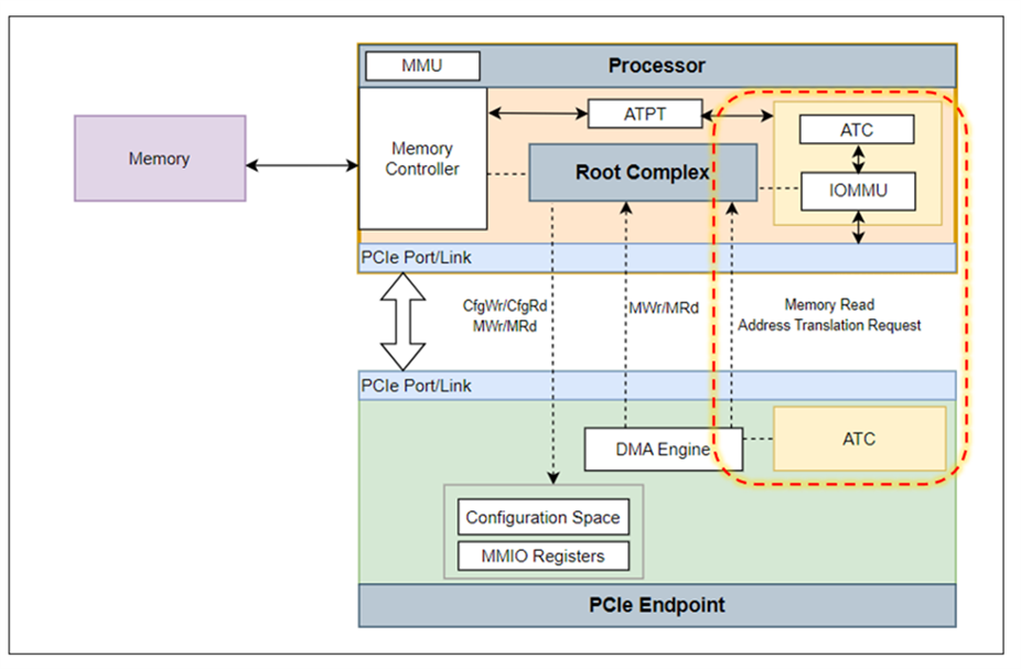
The ATS, or Address Translation Services, supports translation DMA (Direct Memory Access) addresses to addresses on the PCIe device. It is comprised of many different sub-components that work together to provide fast, low-latency address translation.
The ATS relieves the CPU from having to perform these address translations itself. It runs as a set of hardware components that bypass the CPU.
Translation Agent
The Translation Agent is a software component running on the host that translates addresses on behalf of the host for PCIe devices. It uses data structures like page tables and Translation Lookaside Buffers (TLB) to perform the virtual-to-physical memory translations.
Address Translation Cache
The ATC is a cache on the device that stores translations between virtual and physical addresses. This cache stores results from the TA and allows translations to be performed with much lower latency.
Address Translation Protection Table
The ATPT is a data structure used to store page tables for an address translation. It contains the set of address translations accessed by a Translation Agent to process PCIe requests.
References:
- https://www.intel.com/content/www/us/en/docs/programmable/683686/20-4/address-translation-services-ats.html
- https://community.cadence.com/cadence_blogs_8/b/fv/posts/navigating-the-complexity-of-address-translation-verification-in-pci-express-6-0
Root Complex

A Root Complex device connects the CPU and memory subsystem to the PCIe switch fabric. It generates transaction requests on behalf of the CPU, which is interconnected through a local bus. Root Complex functionality may be integrated in the chipset and/or the CPU.
All CPU<->Memory operations happen inside of the root complex. The CPU may attempt to access something on the PCIe bus, in which case the root complex will forward the request to the PCIe controller, from where the controller will route the request to the proper PCIe endpoint.
References:
CLI Tools
lspci
$ lspci
00:00.0 Host bridge: Advanced Micro Devices, Inc. [AMD] Starship/Matisse Root Complex
00:00.2 IOMMU: Advanced Micro Devices, Inc. [AMD] Device 164f (rev 01)
00:01.0 Host bridge: Advanced Micro Devices, Inc. [AMD] Starship/Matisse PCIe Dummy Host Bridge
setpci
NAME
       setpci - configure PCI devices

SYNOPSIS
       setpci [options] devices operations...

DESCRIPTION
       setpci is a utility for querying and configuring PCI devices.

       All numbers are entered in hexadecimal notation.

       Root privileges are necessary for almost all operations, excluding reads of the standard header of the configuration space on some operating systems.  Please see lspci(8) for details on access rights.
dmidecode
Use dmidecode to read verbose information on all hardware being used on the computer. This tool decodes the SMBIOS table in a human-readable format.
The acronym DMI refers to the Desktop Management Interface which is a closely-related standard to SMBIOS that dmidecode was originally written for.